

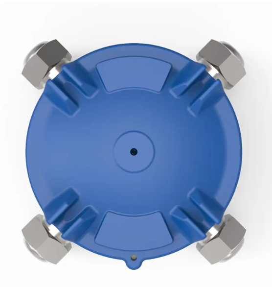
Class I, Division 2 environments require careful electrical planning because flammable gases or vapors may be present under abnormal operating conditions. Conduit routing, enclosure selection, conductor preparation, and grounding all affect installation safety. Proper junction box wiring helps maintain organized electrical connections and supports safe inspection and maintenance. Understanding the applicable electrical code and hazardous-area classification helps engineers, contractors, and maintenance teams plan wiring systems that suit the facility’s operating conditions.
Understand the Hazardous Area Classification
Class I, Division 2 generally describes locations where flammable gases or vapors are not expected during normal operation but may occur because of equipment failure, accidental leakage, or abnormal conditions. This classification affects the electrical equipment and installation methods permitted in the area.
Before selecting components, engineers should review hazardous-area drawings and process documentation. These records identify classified boundaries and the substances involved. Gas characteristics, operating temperatures, ventilation, and potential release points can affect equipment selection. Contractors should confirm the classification with the responsible electrical engineer instead of relying on general descriptions of the facility.
Choose Enclosures That Match Site Conditions
An enclosure must suit the classified location, environmental conditions, and electrical installation requirements. Buyers should check its certification, permitted hazardous-area use, ingress protection, material compatibility, and temperature limitations. Equipment designed for ordinary industrial areas may not be suitable for a classified location, even when its housing appears durable.
For an exterior electrical junction box, engineers should also consider rain, dust, sunlight, corrosive substances, and temperature changes. Outdoor installations may need protection against moisture entering through cable entries or damaged seals. The enclosure rating and approved installation conditions should be reviewed together, because a suitable housing alone does not establish compliance.
Plan Conduit Routes Around Access and Protection
Conduit routing should follow approved drawings and applicable electrical codes. Installers need to consider cable paths, equipment access, support spacing, bends, and possible mechanical damage. Excessive bends can make conductor pulling difficult and may damage insulation. Poorly supported conduit can place stress on fittings and enclosure entries.
The route should allow technicians to inspect connections and perform maintenance without unnecessary dismantling. Where conduit crosses areas exposed to vibration or impact, the design should account for movement and physical protection. Fittings must match the conduit type, enclosure entry, and hazardous-location requirements. Required seals should be installed at the locations specified by the applicable code and equipment instructions.
Make Electrical Connections With Care
Correct junction box wiring begins with confirming the circuit schedule, conductor sizes, voltage, and expected load. Conductors should have suitable insulation ratings and current-carrying capacity. Installers should identify each conductor clearly and leave enough working length for approved terminations without overcrowding the enclosure.
Before making connections, electricians should isolate the circuit and verify the absence of voltage with appropriate test equipment. Facility lockout and tagout procedures must be followed. Terminals should match the conductor material and size. Connections must be tightened to the specified torque, since loose terminals can overheat while excessive tightening may damage conductors or terminal hardware.
Maintain Reliable Grounding and Bonding
Grounding and bonding provide a path for fault current and help maintain electrical continuity between conductive parts. The installation design should identify how the equipment grounding conductor connects to the enclosure and associated metal conduit. Corrosion, loose fittings, unsuitable connectors, or coatings at contact points can affect continuity.
Installers should follow the applicable code and equipment instructions when making bonding connections. Mechanical contact alone should not be assumed to provide an acceptable grounding path. Inspection and testing can reveal loose connections or discontinuities before energization. Contractors should also coordinate with the facility’s electrical team and document the required test results.
Verify Equipment Suitability Before Procurement
Equipment selection for Class I, Division 2 locations must follow the applicable North American electrical requirements. Engineers should check the area classification, gas group, equipment function, and permitted wiring methods. Depending on the installation, certain general-purpose enclosures may be acceptable when the applicable conditions are satisfied. Explosion-proof construction is not automatically required for every junction box.
Procurement teams should request product specifications, relevant approval documents, and installation instructions. When reviewing equipment from Sunleem EEW, buyers should confirm whether the proposed model meets the requirements of the intended Class I, Division 2 installation. IECEx Zone certification alone should not be treated as evidence of North American Division approval.
Check Junction Box Connections and Sealing Methods
Junction box wiring requires attention to conductor routing, terminal arrangements, and enclosure connections. Installers should verify conductor sizes, terminal ratings, and available wiring space before making connections. Cable entries and conduit fittings must suit the selected enclosure and the wiring method permitted for the classified location.
Sealing requirements depend on the installation design and applicable electrical code. Not every Class I, Division 2 conduit connection requires the same sealing arrangement. Engineers should identify where seals are required and verify the approved installation methods. Grounding and bonding connections should also be inspected before energization.
For industrial projects, Sunleem EEW provides junction box and electrical equipment options that buyers can evaluate against their specifications. Engineering teams should request model-specific documents and confirm applicable approvals before selection. This approach keeps procurement decisions connected to actual installation requirements.
Complete Inspections Before Energization
A pre-energization inspection should cover enclosure integrity, conduit supports, entry fittings, conductor identification, terminal tightness, and grounding continuity. Electricians should check that unused entries are closed with approved components and that covers are properly installed. Missing fasteners, damaged gaskets, and poorly fitted entries should be corrected before the equipment enters service.
Testing and documentation are also important. The responsible team should complete required electrical tests and verify compliance with approved drawings and applicable codes. Records should identify defects and corrective actions. Clear documentation helps maintenance personnel understand circuit arrangements and reduces the risk of mistakes during later repairs.
Put Installation Safety First
Safe conduit and junction box installations depend on correct area classification, compatible equipment, sound wiring practices, effective grounding, and documented inspection. Each measure addresses a different risk, so no single component replaces a complete installation review. Industrial buyers and contractors should confirm technical requirements early and resolve certification questions before equipment reaches the site.
A structured process also supports future maintenance. Accurate drawings, accessible connections, and consistent inspection records help teams identify faults and plan repairs. Treating equipment selection and installation as connected tasks helps project teams develop electrical systems that meet the requirements of the classified environment and remain practical to maintain.
